Blog
Blog
Materials used in Steel Detailing
In the world of steel detailing, understanding the diverse array of materials used is essential for ensuring precision and efficacy in structural design and construction. Rolling mills quickly process metal into products which are known as plain or raw materials. From raw materials to finished products, each component plays a crucial role in shaping the integrity and functionality of steel structures. In this comprehensive guide, we’ll explore the various materials utilized in steel detailing, shedding light on their characteristics, applications, and significance in the construction industry.
- Sections
Raw materials used in the steel industry encompass a wide range of sizes and shapes and each designated by its cross-sectional shape. They can either be hot rolled steel or cold rolled steel. The difference between these two lies in the way that they are fabricated.
a. Hot Rolled Steel
Hot rolled steel is formed by rolling heated steel at high temperatures through a series of rollers. This process allows the steel to be shaped and formed into various sizes and shapes while it is still in a malleable state. Hot rolled steel typically has a rough surface texture and may have slightly rounded edges. It is commonly used in applications where precise dimensions and surface finish are not critical, such as in structural components, railroad tracks, sheet metal, and automotive frames.
While there are many different types of sections that hot rolled steel can be shaped into, not all of them are very readily available. Commonly used material sections include W, C, and angle shapes, each serving distinct purposes in structural design. (Refer Part 1 of the structural steel manual by AISC)
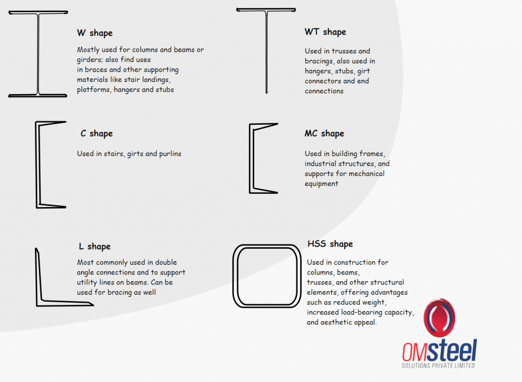
- W section or wide flange section has a flange width which is common on both sides. They are the most commonly used shape.
- The WT section is made by splitting the ‘W’ shape at mid-depth in a cross-section view.
- In a channel section or a C section (also known as American standard channels), a web is connected to two equal flanges at the both ends.
- Multi-channel or MC sections(also known as miscellaneous channels) are similar to ‘C’ sections, the main difference is the width of the flange and flange slope.
- L or Angle shapes in steel structure refers to structural steel members that have two legs forming a right angle.The legs are of equal thickness and either equal or unequal leg sizes. They are commonly known as ‘angle sections’ or simply ‘angles’.
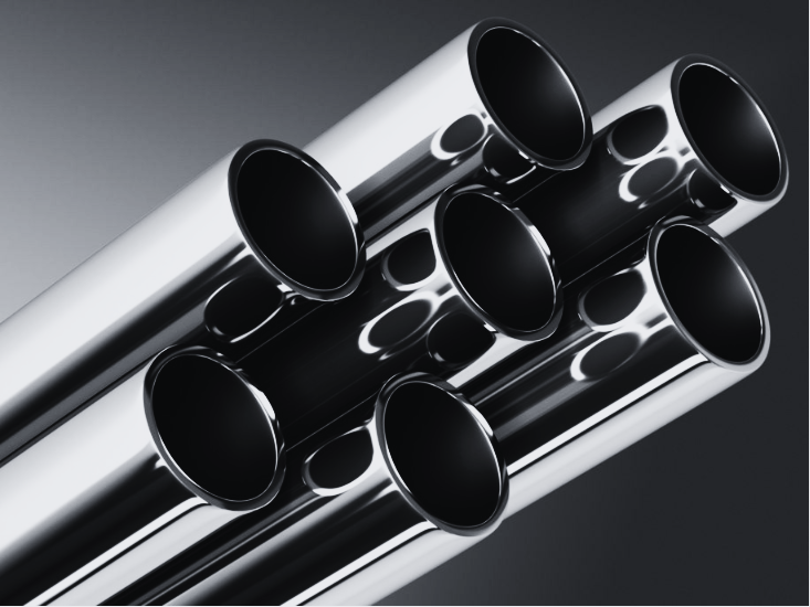
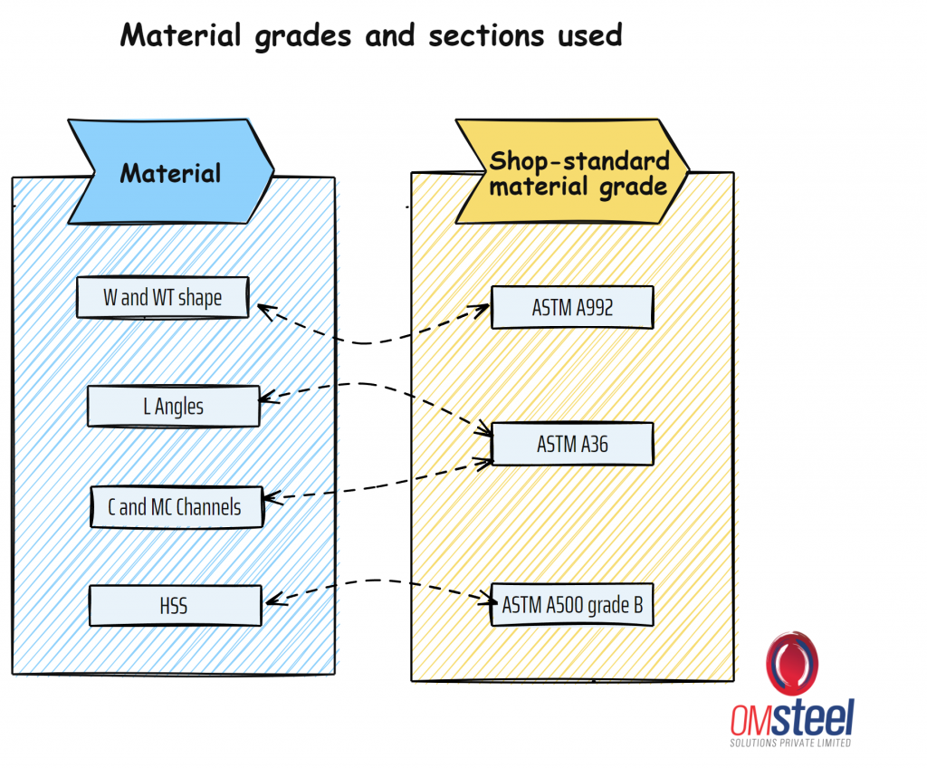
- Hollow Structural Sections (HSS), formerly known as Tube-shaped steel (TS), are steel tubes with hollow cross-sections, typically square, rectangular, or circular. They are used in structural applications where strength, durability, and versatility are required.
b. Cold Rolled Steel
Cold-formed steel (CFS) refers to steel products that are formed at room temperature through various shaping processes, such as rolling, pressing, or stamping. Unlike hot-rolled steel, which is formed at high temperatures, CFS is produced using cold-working methods, making it more economical and precise for certain applications. Common products made from cold-formed steel include studs, joists, decking, and framing components used in construction projects.
Cold-formed steel offers several advantages, including high strength-to-weight ratio, dimensional accuracy, and uniformity of properties. It is also recyclable, making it an environmentally friendly choice for sustainable construction practices. Additionally, CFS can be engineered to meet specific design requirements, offering versatility and flexibility in construction projects.
2. Mill Tolerance
Mill tolerance refers to permissible deviations from published dimensions and cross-sectional profiles listed in the manual of steel construction. These variations, though negligible in small shapes, become more pronounced in larger sections due to the manufacturing process. Factors such as wear on rolling equipment contribute to deviations, necessitating allowances for variations in cross-sectional area, weight, and geometry. (Refer Part 1 and Part 1 table 1-22 and 1-26)
3. Material Grades
Understanding material grades is crucial for selecting appropriate materials based on design requirements and performance criteria. Structural steel is mainly composed of iron and also consists of trace amounts of carbon and manganese to provide strength and ductility.
Structural steel is available in various grades, distinguished by yield strength. Yield strength is the maximum stress steel can endure without undergoing permanent deformation or failure.It is measured in kips per square inch (ksi), where 1 kip = 1000 pounds.
The following are some commonly used grades:
- ASTM A992 with yield strength of 50 ksi, is predominantly utilized for W shapes in both beams and columns, making it a preferred choice for structural applications requiring high strength and stability.
- ASTM A36 with a yield strength of 36 ksi, and is commonly used for L (angles) and C and MC (channels)
- ASTM A572, offered in a variety of yield strengths, stands out as a high-strength, low-alloy steel. This versatile material is prized for its exceptional strength-to-weight ratio, making it suitable for a diverse range of applications in structural engineering.
- ASTM 588 with a yield strength of 50 ksi. This steel is often referred to as self-weathering because it undergoes oxidation upon exposure to air, resulting in the formation of a thin layer of rust on the surface, typically only a few thousandths of an inch thick. As a result, there is no requirement for painting this type of steel. Additionally, this natural rust layer serves as a protective barrier against further corrosion, enhancing the durability and longevity of the steel structure.
(Refer Part 16.3 section 6, Part 2 and table 2-4 to 2-6)
4.Drawings, views and projections
Beginning the exploration of steel detailing requires a thorough understanding of various projection methods and design principles. In this overview of drawings, views, and projections in the context of steel detailing, we’ll delve into techniques like orthographic and isometric projections. Additionally, we’ll uncover the pivotal role of design drawings, serving as detailed blueprints for the intricate structural components that form the backbone of steel structures.
a.Orthographic projection
An orthographic projection is a technique used in engineering and technical drawing to represent a three-dimensional object in two dimensions. In this projection method, the object is depicted using a series of 2D views, typically from the front, top, and side, each showing the object as if viewed from a different direction. These views are positioned relative to each other to accurately represent the object’s shape, size, and features without distortion.
b. Isometric projection
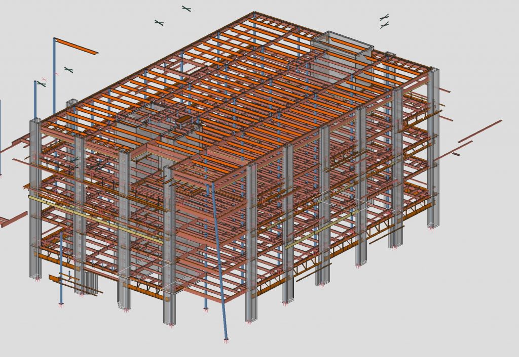
An isometric projection is a method of representing a three-dimensional object in two dimensions. Unlike orthographic projections, which display the object as separate 2D views from different directions, an isometric projection shows the object from a single viewpoint. This method creates a more realistic and visually appealing representation of the object, making it easier to understand its form and spatial relationships.
5. Design Drawings
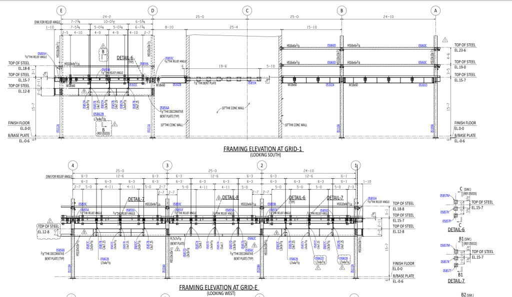
In the steel industry, design drawings serve as detailed blueprints for the structural components of a building or structure. There are two types of design drawings, architectural and structural, which are created by architects or engineers, outline essential information such as the size, shape, placement, and configuration of steel elements like beams, columns, and connections. Detailers must thoroughly understand the information provided in design drawings, including specifications for grades, materials, bolts, welds, finishes, and surface preparations.
It’s crucial for detailers to communicate with the engineers who created the drawings to clarify any unclear or missing information. Design drawings typically include specifications that dictate certain detailing constraints, ensuring that detailers adhere to specific standards and requirements throughout the detailing process. Additionally, detailers must pay close attention to elevation definitions, either by establishing arbitrary values for floors or by referencing actual heights above sea level, to accurately position structural elements.
Foundation plans, integral components of design drawings, depict the building’s footings, foundation walls, and grid system. The grid system aids in locating the centre of columns and ensuring proper dimensioning, especially for the bottom of columns, which directly affects column lengths. Detailers must also consider factors like footing elevation discrepancies and the use of grout to correct footing imperfections before column installation, further emphasising the importance of meticulous attention to detail in interpreting and implementing design drawings.
a. Erection Drawing
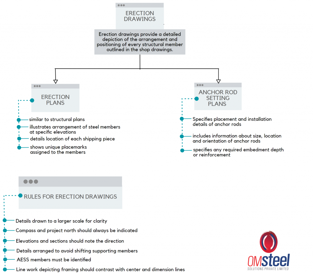
Erection drawings provide a detailed depiction of the arrangement and positioning of every structural member outlined in the shop drawings. Erection drawings are made before the actual shop drawings. Erection drawings can be classified into two types:
1) Erection plans
Erection plans are similar to structural plans and show the arrangement of members at a particular elevation. They will also show the unique placemark that has been assigned to the members. This is so that the location of every shipping piece, which may be an individual member or an assembly of several pieces is identified.
2) Anchor Rod Setting plans
These drawings specify the placement and installation details of anchor rods, which are used to secure structural elements to the foundation or supporting structure. Anchor rod setting plans typically include information about the size, location, and orientation of anchor rods, as well as any required embedment depth or reinforcement.
b. Shop Drawing
Also known as shop assembly or shop detail drawings, these drawings provide detailed instructions for fabricating and assembling individual structural components in the workshop or fabrication facility. Shop erection drawings include dimensions, material specifications, welding details, and other information necessary for manufacturing and assembling the components according to the design specifications.
These drawings are essential for ensuring the accurate and safe erection of structural steel components on-site. Each of them serve a specific purpose in the construction process
6. Advanced Bill of Materials (ABM)
The Advanced Bill of Material (ABM) plays a pivotal role in ensuring the smooth execution of construction projects. ABM serves as the blueprint that guides fabricators in placing orders to steel mills and receiving materials promptly to meet project deadlines. One of the critical aspects of ABM is accounting for cutting mill tolerances, which vary depending on the project’s specifications. To avoid delays and material shortages, detailers and fabricators often order extra lengths of steel to accommodate these tolerances effectively.
Key parameters included in ABM are sequence, steel grade, member type, line or serial number, quantity, length, and weight. The sequence parameter is particularly crucial as it dictates the order in which materials are transported to the job site, ensuring efficient logistics and installation processes.
Additionally, the anchor rod setting plan typically marks the inception of steel fabrication projects, outlining the precise placement and configuration of anchor rods to secure structural elements in place.
In conclusion, a thorough understanding of the materials used in steel detailing, is essential for ensuring the integrity and functionality of steel structures. With an array of sections and material grades available, detailers must carefully select the most suitable options based on design requirements and performance criteria. Although there is a plethora of options, there are standards set in place and commonly used grades for each type of structural member as referenced above. Additionally, proficiency in interpreting design drawings and projections is paramount, as they serve as the blueprint for the intricate structural components that form the backbone of steel structures. Stay tuned for more insights into the fascinating world of steel detailing and structural engineering.