Steel Detailing Services
Steel Detailing Services
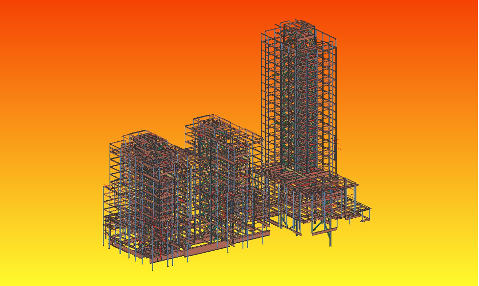
3D Modelling using SDS/2 including connection design
At Om Steel, we handle each project with the highest degree of perfection and precision. Quick delivery with extra focus on quality is what sets us apart from the rest. When it comes to anchor bolt layout and embed details, most vendors spend a lot of time in modelling. This extends the project timeline unnecessarily. Any errors in the initial modelling further delays your project.
Years of experience and expertise has helped us design a quick and efficient way to help you with this.
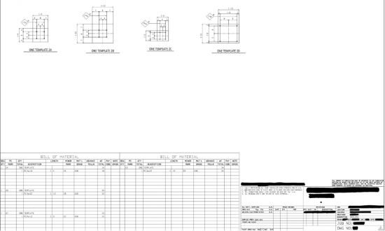
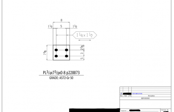
To start with, we have pre-designed a variety of anchor bolt drawings which we use as templates. This helps us save time spent on modelling.
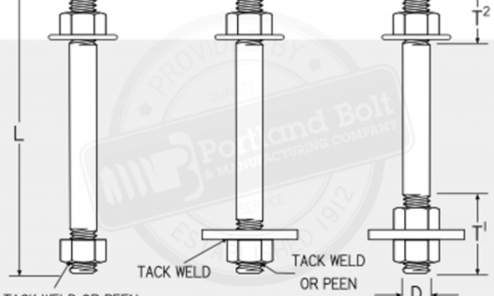
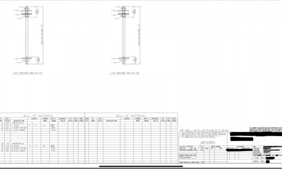
SDS/2 will not give parameters like thread length, diameter of bolt, Anchor bolt length by default. We have developed our own templates and our employees are trained to place such information on detail sheets for the benefit of fabricators.
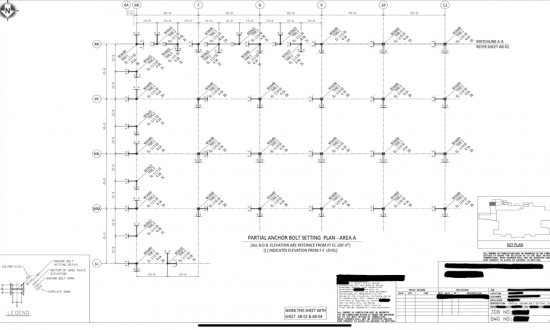
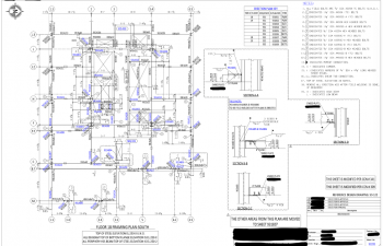
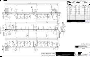
Addition of grid lines and Bolt details to the Anchor Bolt Layout so that the erector can locate and erect them easily.
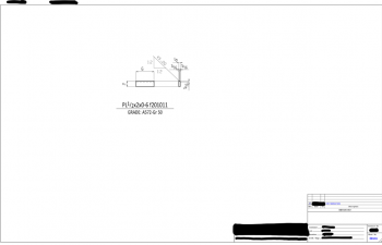
Addition of Anchor Bolt embed and projection length on detail sheets in a manner similar to what is shown on structural drawings. Again for the benefit of the erector and fabricator.
Detailed embed information along with structural layout plans for easy understanding and placement. All these are not default outputs of the software, they are done by our trained professionals.
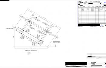
Certain portions of the structural drawings need to be presented in detail sheets, specially to understand field welding and attaching of embeds, support for walls and girts, wall anchors and many more. Using TIFF image format we are able to extract the sketch from design drawings and place it on the detail sheets.
Easily import IFC, AutoCAD drawings into SDS/2
Struggling to get a customised IFC model that fits your project perfectly?
One of the most basic requirements for starting a project is having a IFC model tailored to your requirements. Yet, many vendors struggle with providing it accurately. As a project manager, you obviously know that any error at this stage can lead to huge chaos later.
At Om Steel, we are extra careful to make this step of the process easy, efficient and error-free.
You need the boundaries of the entire model to be at certain coordinates. Using Revit we adjust the IFC model to those coordinates. We merge different IFCs from different consultants to create a standard reference model.
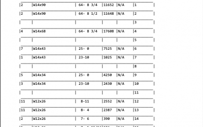
Check the Advance Bill of Materials. Avoid discrepancies later.
Worried about hidden costs and overages when working on a project?
One of the most common causes of grief and stress at the end of a project is being handed a bill of extra spends. While most project managers are prepared for a 5-10%extra spend, things get uncomfortable if it is an amount you weren’t prepared for.
Most vendors and service providers put off conversations like this till the very end, to avoid disruptions during the project. But it only soars the relationship in the end, causing more trouble for everyone involved.
At Om Steel, we always emphasis on clear and transparent communication.
There are certain changes that come about after the ABM is sent and before the shop release. To ensure this change is highlighted and there is no discrepancy in the BOM we have developed an automated work flow.
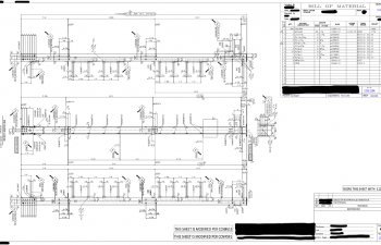
Truss ABM’s raw output from SDS can be quite tricky to decipher and we ensure that we always keep all materials of a single truss in one page. We do not mix materials of different types of trusses, even if they are same, for keeping track of changes of a particular type of truss as job progresses.
Customise your CNC Information and Fabtrol Export
A lot of vendors have pre-set CNC templates that cannot be customised or even modified. This leaves project managers with little to no leeway in enhancing their projects. It is also creatively restricting.
At Om Steel, we’ve found the perfect solution to your problem.
We modify our CNC set up based on fabricator’s requirements. For example, some wants scribing of piecemarks, some do do not want. We modify set up accordingly.
SDS/2 does not generate CNC for the bent plate if it has its leg cut flush for a certain length. In such scenario, we keep its leg to “k” value of the material instead of cut flush and then generate CNC.
We had requirement of a client, to have all the information including paint finish code on Kiss for Strumis—This was done by editing material & inputting the required codes in the fields to have all the information on KISS file.
Generate Accurate Detail Sheets and Erection Plans
Truss detailing is time-consuming and tedious. It is an integral part of your project. And sadly, this is also the one step where it’s most common to overlook mistakes.
When working with a third-party vendor or a partner, project managers are extra careful about this. To help solve this problem, Om Steel has come up with a unique solution.
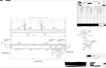
We had a prior review and identified the exact changes in each truss so that once a master truss done, most of the dimensions can be copied and the only change needs to be cleaned up. Also, SDS does not give camber calculation for a cambered truss. We have a worksheet to calculate the camber values.
To avoid errors from actual detail & sections Vs Bill of material, we introduced a check where a support team verifies drawings for this.
For any missing member for detailing and sheet loading, we introduce a report named “ON SHEET” & “SEQUENCE Check” so that nothing gets left out.
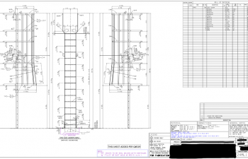
In case of misc detailing, like ladders or handrails, SDS practically do not give much details. We work manually, spending considerable time to get a proper presentation for fabrication ease of shop.
Get Easy-To-Understand 3D Modelling using SDS/2 including connection design
Worried about receiving confusing 3D models and connection designs?
Most vendors try to pass-off pre-made or off-the-shelf designs for every project. This creates trouble in the future.
At Om Steel, we manually redesign whatever is needed.
SDS does not give any truss diagonal or end connections. We need to work manually to design each joint of truss.
SDS/2 has limitations at some of the connections where all the capacities are adequate but still it shows failed connection due to framing situation—In such cases, we add supporting notes on calculations to prove it as adequate.
In many cases, SDS gives higher weld or bolts per load. We have to check , modifying parameters to see whether it can pass with lower values or not.
Speed Up Projects by Getting Gather Sheets of All Material
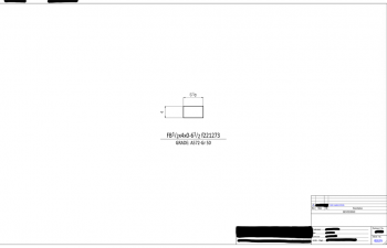
At Om Steel, we provide gather for almost all materials. Even for the round HSS with cuts, we provide its unfold view for shop. This makes it easier for project managers to set timelines and end-dates for a project.
We need to show preparation of any materials by cutting sections after going into details. SDS never gives the preparation of any material from model directly.


