

In structural steel design, the way beams and columns are connected determines how forces are transferred throughout a framing system. Among the most critical and most technically demanding of these are moment connections. Unlike simple or shear connections, moment connections are engineered to transfer not only shear forces but also bending moments between members. Understanding their classification, design requirements, and detailing standards is essential for any structural engineer working with steel construction in the United States.
What Is a Moment Connection?
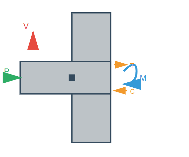
Per the AISC Specification for Structural Steel Buildings, beam-to-column connections are classified based on their rotational stiffness and moment capacity. A moment connection, formally known as a FR (Fully Restrained) connection, is designed and detailed to transfer moment with negligible relative rotation between the connected members. This is in contrast to PR (Partially Restrained) connections, which permit measurable rotation while still transferring some degree of moment, and simple connections, which are assumed to transmit shear only and allow free rotation.
The AISC Manual for Structural Steel Construction identifies moment connections as essential in moment frames, the primary lateral force-resisting systems in steel buildings. These connections must be capable of developing the full plastic moment capacity of the connected beam in many seismic and wind design scenarios.
Types of Moment Connections
The AISC Manual and AISC 358 (Prequalified Connections for Special and Intermediate Steel Moment Frames) describe several standard moment connection configurations:
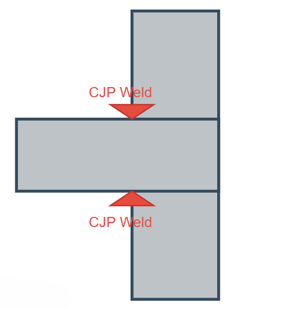
1. Welded Unreinforced Flange – Welded Web (WUF-W)
This connection uses complete-joint-penetration (CJP) groove welds at both beam flanges directly to the column flange, combined with a welded web plate. The web connection is made with fillet or groove welds. This type is common in moment frames and relies on quality weld access holes to reduce stress concentrations.
2. Bolted Flange Plate (BFP)
In this configuration, flange plates are shop-welded to the column and field-bolted to the beam flanges using high-strength bolts (ASTM A325 or A490), while the web connection is made with a bolted shear tab. This design is highly favored for its ease of field erection and inspectability.
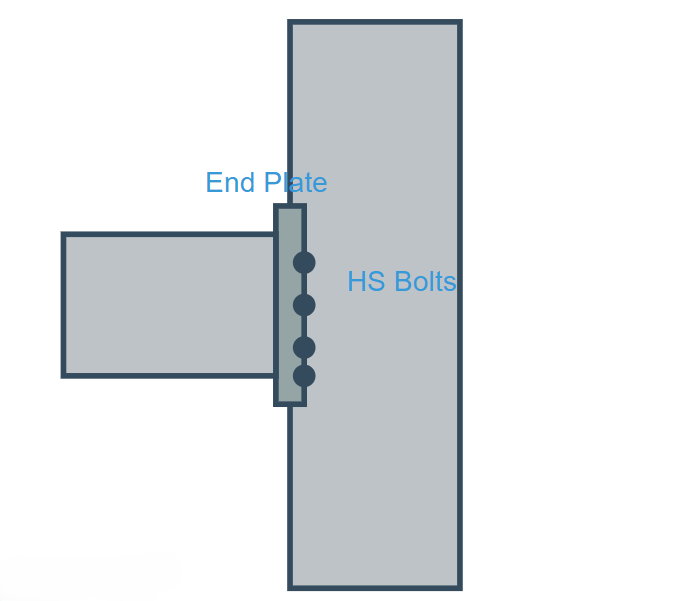
3. Extended End-Plate (EEP)
Extended end-plate connections use a steel plate shop-welded to the beam end and field-bolted to the column flange. AISC 358 identifies four standard configurations: the 4E, 4ES, 8E, and 8ES, differing in the number and arrangement of bolts. These connections are valued for their architectural appeal (no exposed welds in the field), but require precise fabrication.
4. Reduced Beam Section (RBS)
Also known as the “dogbone” connection, the RBS reduces the beam flanges near the connection zone to deliberately relocate the plastic hinge away from the weld. This is a seismically preferred detail per AISC 358 and is common in Special Moment Frames (SMF) and Intermediate Moment Frames (IMF).
Detailing Requirements Per AISC Detailing for Steel Construction
The AISC publication Detailing for Steel Construction provides comprehensive guidance on how moment connections should be drawn and communicated across the project team. It defines the responsibilities of the Structural Engineer of Record (SER), the Fabricator, and the Detailer, and provides standard details and notation practices.
Key detailing considerations for moment connections include:
- Weld access holes – Geometry and finish requirements for CJP groove welds in beam flanges
- Backing bars – Whether to remain or be removed; removal and back-gouging is required in seismic applications
- Continuity plates (column stiffeners) – Required when column flange bending or web yielding governs; thickness and weld sizing are detailed per AISC standards
- Doubler plates – Used to reinforce the column panel zone against shear; must be detailed to account for fit-up with column k-zone
- Shop vs. field welds – CJP welds at beam flanges are typically field welds; flange plates and shear tabs are shop-welded and field-bolted
The manual also emphasizes the need for erection clearances, match-marking of field connections, and clear indication of camber and bearing conditions on connection details. Proper coordination between the SER’s contract documents and the fabricator’s shop drawings is vital to avoid costly field modifications.
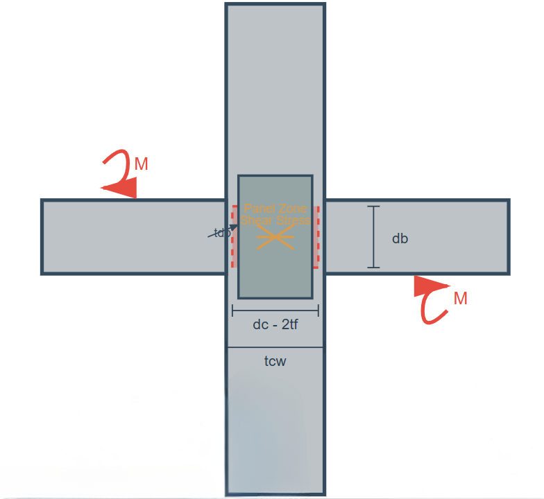
Panel Zone and Column Stiffener Design
One often underestimated aspect of moment connection design is the column panel zone, the region of the column web bounded by the continuity plates (if any). The AISC Manual address panel zone shear design explicitly. When the applied panel zone shear exceeds the available shear strength of the column web, a doubler plate welded to the web is required. This detail must be carefully coordinated to avoid interference with column flange welds and access holes.
Quality and Inspection Considerations
Moment connections, particularly those involving CJP groove welds, require rigorous inspection. The AISC Manual references AWS D1.1 for structural welding and AWS D1.8 for seismic applications. Ultrasonic testing (UT) and visual inspection are the primary QC methods. The AISC Code of Standard Practice governs the responsibilities and communication protocols between the fabricator, erector, and owner’s inspector.
Moment connections are among the most carefully engineered details in structural steel construction. The AISC Manual for Structural Steel Construction, the AISC Specification, and Detailing for Steel Construction together provide a comprehensive and coordinated framework for their design, detailing, and quality assurance. Engineers must understand not only the force flow through each connection component but also the practical constraints of fabrication and field erection. With proper application of AISC standards, moment connections form the backbone of robust, ductile, and economical steel structures.