

Cantilevers are among the most elegant and practical structural elements in modern steel construction, projecting boldly into space with support from only one end. Whether you’re designing a dramatic building overhang, a balcony, or an industrial platform, understanding cantilever behavior according to the American Institute of Steel Construction (AISC) standards is essential for safe and efficient design.
What is a Cantilever?
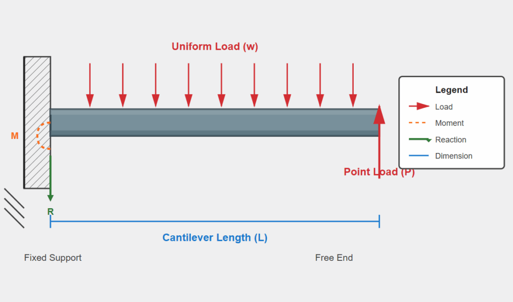
A cantilever is a structural member that extends beyond its support, fixed at one end while the other end is free. This configuration creates unique loading conditions that distinguish cantilevers from simply supported beams. The fixed support must resist both vertical reactions and a fixing moment, making the connection design critical to the cantilever’s performance.
Key Design Considerations per AISC Standards
Load Distribution and Moment Diagrams
According to the AISC Manual for Structural Steel Construction, cantilevers produce negative moments (tension at the top fiber) throughout their length, opposite to the positive moments found in simply supported beams. This reversal has significant implications for member selection and bracing requirements. The maximum moment occurs at the fixed support and equals the load multiplied by the cantilever length for uniform loads, or the concentrated load multiplied by its distance from the support for point loads.
Deflection Control
Deflection is often the governing factor in cantilever design. The AISC Specification doesn’t mandate specific deflection limits, leaving this determination to the engineer’s judgment based on the structure’s intended use. However, typical practice limits live load deflection to L/180 or L/240 for cantilevers, where L is the cantilever length. Dead load deflection may be limited to L/120. Because cantilever deflections are approximately three times greater than equivalent simply supported beams under the same loading, careful attention to serviceability is paramount.
Lateral-Torsional Buckling
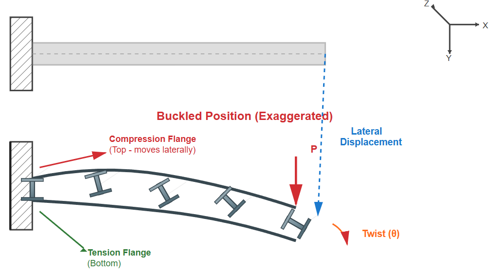
One of the most critical aspects of cantilever design involves lateral-torsional buckling. According to AISC specifications, cantilevers are particularly susceptible to this failure mode because the compression flange (the top flange in typical cantilevers) is often unbraced. The effective length factor for lateral-torsional buckling can be significantly greater than 1.0 for cantilevers, sometimes approaching 2.0 depending on the end conditions.
Chapter F of the AISC Specification for Structural Steel Buildings provides detailed provisions for calculating the nominal flexural strength considering lateral-torsional buckling. For cantilevers, special attention must be paid to the unbraced length (Lb), which typically extends the full cantilever length unless intermediate bracing is provided.
Bracing Requirements
The AISC Manual emphasizes that adequate bracing is essential for cantilever stability. According to the specifications, bracing the compression flange at the fixed support is crucial, but designers should also consider bracing at intermediate points along the cantilever length for longer spans. The required bracing strength and stiffness must meet the provisions outlined in Appendix 6 of the AISC Specification.
For cantilevers supporting floors or roofs where the deck provides continuous lateral support to the compression flange, lateral-torsional buckling concerns are typically eliminated. However, during construction before the deck is attached, temporary bracing may be necessary.
Connection Design Requirements
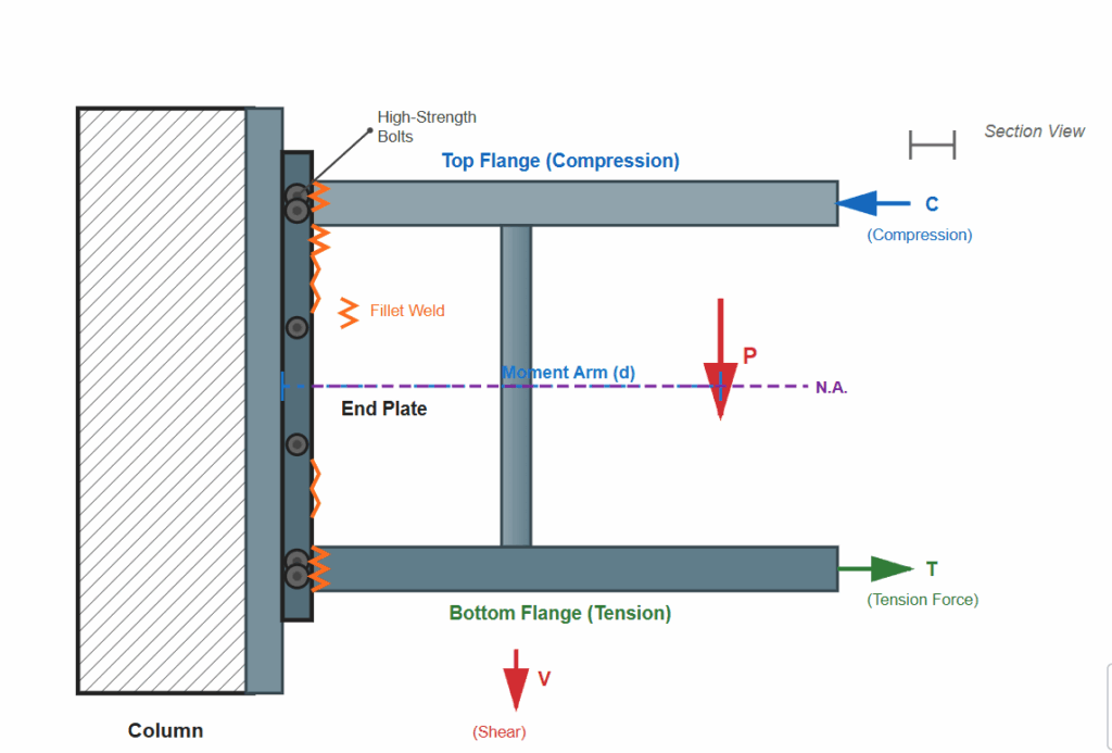
The AISC Detailing for Steel Construction standards provide specific guidance for cantilever connections. The fixed-end connection must develop the full moment capacity required by the design loads, which often necessitates moment connections using bolted end plates, welded connections, or a combination of both.
Connection design must account for both tension and compression forces in the flanges, as well as shear in the web. The AISC Manual’s connection tables provide standard configurations, but cantilever connections often require custom design due to their unique force distributions. All welds and bolts must be detailed to meet the requirements of the AISC Specification, with particular attention to proper weld sizing and bolt tensioning procedures.
Special Cases and Applications
Cantilevered Beams in Framing Systems
Cantilevers are often integrated into larger framing systems to reduce positive moments in adjacent spans. This strategic use can lead to more economical designs by evening out the moment distribution across continuous beams. The AISC Manual provides moment coefficients and analysis methods for these multi-span configurations.
Gerber Systems
Advanced applications include Gerber systems (also called cantilever-suspended span systems), where cantilevers support simple spans through hinged connections. These systems are detailed in the AISC Manual and offer advantages in long-span construction by creating statically determinate structures that accommodate differential settlement.
Practical Design Steps
When designing a cantilever per AISC standards, engineers should follow this systematic approach: calculate factored loads using appropriate LRFD or ASD load combinations; determine maximum moments and shears; select a trial member size; check flexural strength considering lateral-torsional buckling; verify shear capacity; calculate and evaluate deflections; design the fixed-end connection; and specify proper bracing locations and requirements.
Cantilever design according to AISC standards requires careful consideration of multiple factors including strength, stability, serviceability, and constructability. The interplay between moment capacity, lateral-torsional buckling resistance, deflection control, and connection adequacy makes cantilevers among the more challenging elements to design properly. However, by following the comprehensive guidelines provided in the AISC Manual for Structural Steel Construction, Specification for Structural Steel Buildings, and Detailing for Steel Construction standards, engineers can create safe, economical, and elegant cantilever solutions for diverse structural applications.
Understanding these principles ensures that cantilevers perform as intended throughout their service life, supporting loads safely while meeting all serviceability requirements. Whether designing a modest balcony or a dramatic architectural feature, mastery of AISC cantilever provisions is an essential skill in the structural engineer’s toolkit.