

In structural steel construction, clear communication between design, fabrication, and erection teams is essential. One of the most critical tools used to achieve this clarity is the erection drawing. These drawings serve as a bridge between the detailing office and the site, providing field crews with the information they need to assemble the steel structure quickly, safely, and accurately.
What is an Erection Drawing?
An erection drawing is a field-installation or member-placement drawing prepared by the fabricator. It shows the location and attachment of each shipping piece, which could be a single steel member or a subassembly shipped as one unit. These drawings are created specifically for the erector and are not intended to include the erection methodology (like crane use or temporary bracing). Instead, they focus on what goes where and how it connects.
These drawings typically include:
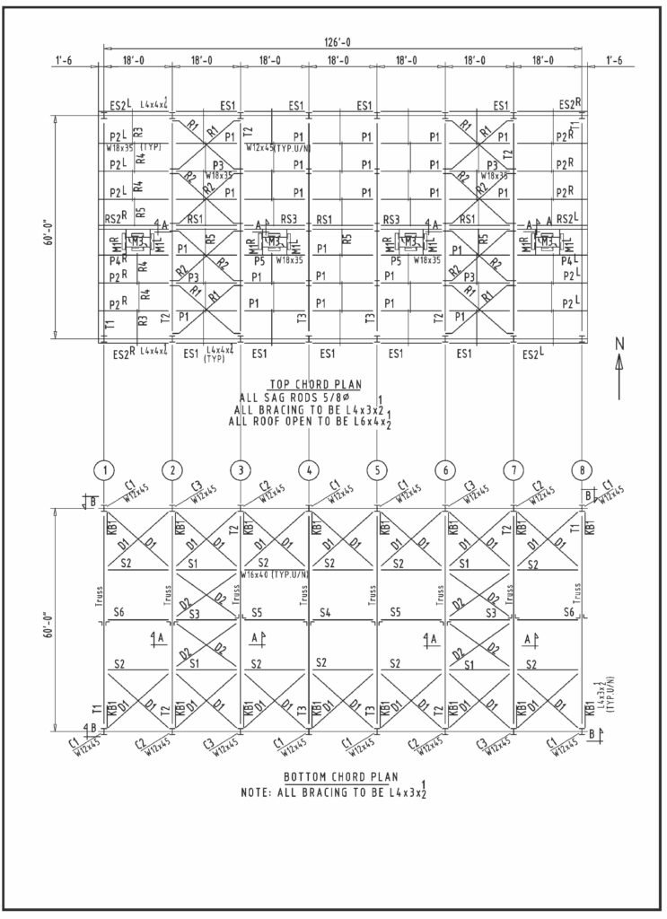
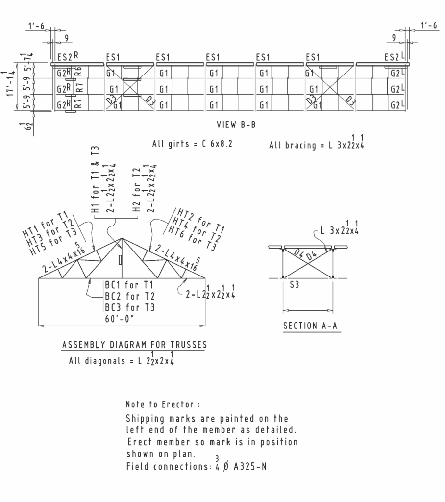
- Plan, elevation, and sectional views of the structure.
- Member placement with erection or shipping marks.
- Connection details relevant to field assembly.
- Enlarged views or sections for clarity.
- Notes on field welding, bolting, and installation.
In modern workflows, 3D models or isometric views are also used to provide a spatial understanding of how pieces come together.
Why Are Erection Drawings Needed?
Without a detailed erection drawing, even the best-fabricated steel pieces can turn into a logistical nightmare on-site. Here’s why these drawings are essential:
- Speed and Accuracy: Erection drawings enable the erector to know exactly where each member goes, minimizing delays caused by confusion or guesswork.
- Avoiding Re-handling: By sequencing the structure and showing division areas, erection drawings allow for strategic shipping and unloading of steel pieces, reducing on-site re-handling.
- Coordination: They offer clarity on how pieces connect and align, eliminating the need for erectors to cross-reference complex shop drawings.
- Early Planning: Erection drawings often begin before shop detailing starts. This helps ensure all necessary field installation considerations are accounted for from the outset.
Some fabricators also use these drawings as progress trackers wherein team members “mark off” each completed detail, helping project leaders monitor detailing progress and manage schedules more efficiently.
More Than Just Framing: Anchor Rods, Grillage, and Embedment Plans
Erection drawings aren’t limited to showing structural steel frames. They also include supporting plans that must be issued early in the project for concrete and masonry work, often before any steel erection begins. These include:
- Anchor Rod Plans: These locate cast-in-place anchor rods and loose base plates that tie the steel frame to the foundation.
- Grillage Plans: These show the layout of grillages, which are beams embedded in foundations to support heavy column loads. Multiple tiers may be used and detailed accordingly.
- Embedment Plans : These locate embedded plates or shapes in concrete or masonry walls to which steel will eventually be connected. This may also include support items for joists, decking, or grating.
These supporting plans are often referred to collectively as embedment drawings in the AISC Code of Standard Practice.
Can the Design Drawings Be Used as Erection Drawings?
In some cases, yes, but only with permission. Reproductions of design drawings may be used as erection drawings under AISC Code Section 4.3, provided they:
- Are legible and to scale.
- Are free from unnecessary or confusing details.
- Clearly identify shipping pieces with line breaks and marks.
- Have extraneous information removed and do not reference the original design firm.
However, embedment drawings (like anchor rod or grillage plans) should not be reproduced from design drawings. These need to be specifically prepared for accurate placement in concrete work.
Best Practices and Guidelines for Preparing Erection Drawings
Steel detailers must follow specific industry guidelines and detailing standards when preparing erection drawings. Here are some of the most important ones:
Drawing Layout & Scale
- Erection plans and embedment plans are typically drawn to 1/8” scale, with enlarged details as needed.
- A clear north arrow should be shown on all plans, aligned with design drawings.
- Elevations must indicate viewing direction (e.g., “Elevation Looking East”).
Marking & Representation
- Each member’s piece mark should be placed at the same end as in the shop drawing.
- Use bold, thick lines for steel framing, and differentiate them from centerlines and dimension lines.
- Leave a slight gap where members connect to show they are separate.
Connection and Orientation Notes
- Clearly indicate bolt and weld information, including washer requirements and field instructions.
- Members like angles and channels should include orientation notes (e.g., “leg up” or “web to back”).
- Channel dimensions should be given to the back of the channel, not to the web centerline.
Field-Specific Considerations
- If erection requires temporary shifts of members, this must be noted.
- Notes must be added for AESS (Architecturally Exposed Structural Steel) components.
- For aesthetic or safety reasons, field bolt heads might need to be shown on a specific face.
Sequencing and Adjustments
- If the structure must be erected in a particular sequence (due to clearance, loading, or logistics), it should be highlighted.
- Any field-adjustable components should be clearly shown with final positions and adjustment instructions.
General Notes to Include
- Top of steel elevations.
- Steel grades.
- Welding and bolting specifications.
- Washer types.
- Any special erection start points.
By following these guidelines, erection drawings become reliable, clear, and field-friendly, minimizing miscommunication or rework.
What Happens If There Are No Erection Drawings?
Without erection drawings, a project is essentially flying blind in the field. Here’s what can go wrong:
- Misplaced Members: Incorrect member installation can lead to misalignment, delays, and costly rework.
- Inefficient Erection: Lack of sequencing information causes disorganized delivery and re-handling of steel on-site.
- Field Confusion: Erectors may have to interpret shop drawings or improvise, increasing the risk of errors or safety hazards.
- Schedule Delays: Without clear direction, critical path activities like crane lifts, bolt-ups, and decking can be delayed.
- Compromised Safety: Improper placement of load-bearing elements can pose risks to both the structure and the workforce.
Erection drawings are more than just construction documents. They are essential tools that tie together fabrication, logistics, and field operations. From anchor rod plans that guide foundation steel placement to framing elevations that organize steel sequencing, these drawings support safety, accuracy, and construction efficiency.
For steel detailers, preparing high-quality erection drawings means understanding not only the geometry and connections, but also the real-world conditions of the jobsite. Done right, they help deliver a structure that’s not only buildable , but built better.